


For purposes of this discussion, all flexible current, data, or telecom signal conveyances will be referred to as cables. While some cables may be armor clad (metallic jacketed) or mineral insulated (MI Type), we will be discussing standard polymer jacketed or protected cables. These penetrants are considered to be combustible. Combustible penetrants potentially pose a greater risk than metallic conduits or other noncombustible penetrants. Combustible penetrants may burn out or melt out causing openings to develop within a firestop.![]()
Copper and aluminum are the common metals chosen for conductors simply because they are good conductors of electricity. They are also good conductors of heat however. In a fire, copper or aluminum conductors may also help spread the fire by igniting or burning flammable materials that may be in close proximity. The heat conducted through a copper cable also extends the damage to the cables caused by the fire.
In our modern world, cabling needs are no longer limited to simple two-pair telephone wiring and 12-3 Romex type cable. The cable load in virtually any structure is growing exponentially as complex telephone and computer systems become more commonplace. This changing wiring picture has brought about the need for firestop systems that readily accommodate wiring changes and large volumes of incredibly diverse cable types. At STI, we refer to openings that require frequent retrofit as high traffic penetrations.
The Basics of Firestopping:
We teach people that firestop systems are comprised of three elements: The wall or floor assembly being penetrated. The penetrants themselves… And finally the materials and methods used to seal the penetration. The sequence of normal construction usually dictates that the firestopping is installed last. We won’t go to deeply into the concepts of firestopping at this time. We’ll assume you are already familiar with the basics.
Firestop installations do occur last under normal circumstances. Cable systems involving frequent changing or retrofitting can blur the picture a bit. Successful cable management requires careful planning to accommodate both the cable requirements as well as the fire protection needs.
Firestop Planning:
A well designed cabling system must recognize the unique problems associated with high traffic openings. Cable volumes must be considered along with cable types and sizes. Adequate opening space must be provided in fire-rated barriers to permit not only the present cable loading but also the anticipated future growth requirements.
How much space do I need?
This is one of the most important and at times, difficult issues to grasp. It is vital to the proper design of cable penetrations. Most people vastly underestimate the area of openings that should be provided to suit the wiring needs of a project and give little or no consideration to future expansion. The area of the opening should be able to accommodate the present and future cabling needs along with the appropriate firestop system.
What is an appropriate firestop system?
It depends on the type of penetration and whether their will be cable changes.
Permanent Vs. Retrofittable Firestop Systems:
Sealant systems installed in and around cables represent a more or less permanent installation. These systems are suitable for openings where cables will not be changing. Electrical (power distribution) cables are a good example of cables that will be installed once and seldom changed. These systems are also suitable for penetrations that have exceeded the cable loading of removable systems. Sealant systems also provide a better smoke seal than most removable or retrofittable product systems.
 Firestop putties and pillow/bag/foam block systems represent a class of products designed to facilitate cable changes (retrofits). These products are packed into an opening rather than injected. Thus they tend to be installed around a cable bundle rather than within it. The key word is around. If there is no annulus (space around the cables), these products are inappropriate. How much annulus is enough? It depends on the ability of the product to compensate for burning cable jacketing. UL systems provide some guidelines for maximum loadings but % loadings can be confusing and misleading.
Computing Cable Loading:
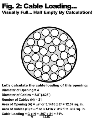
The NEC provides guidelines for calculating the cross sectional area of the cables as a percentage of the cross sectional area of a conduit or tray. Fig. 2 shows how the percentage of fill or cable loading is calculated. Note that in this example, cables are packed to the maximum extent possible for the size of the cables and the shape of the opening involved. What appears to be a totally packed opening, is in reality only half full. While smaller cables and cables of different sizes would nest more tightly and could increase the percentage, 50% is generally the maximum for a round opening.
The problem with this type of calculation is that it does not address the distribution of the cables across the area in question. Keep in mind that we are discussing telecom and data wiring here. While the NEC loading computations are being used, these low voltage installations typically do not fall under the same loading restrictions required for power cable.
Practical Cable Loading Limitations:
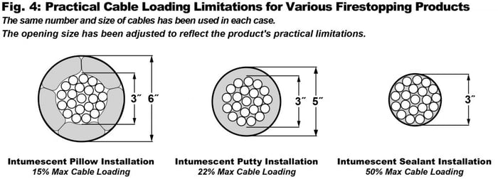
So what are the limits? The limits aren’t always clear. It varies by construction, by cable types and sizes, and the capabilities of the firestop system. Fig. 4 provides an example
using a 3” cable bundle. Since our focus is planning, we’ll use this example to indicate the minimum sleeve size for this size cable bundle using a variety of firestopping methods. The following examples represent our recommendations for maximum loadings. In some cases, our actual tested systems may be rated for higher loadings, but we feel that these are the practical limits. IT SHOULD BE NOTED THAT THIS EXAMPLE IS BASED UPON STI’S FIRESTOPPING PRODUCTS. OTHER PRODUCTS MAY NOT PROVIDE SIMILAR PERFORMANCE AND MAY REQUIRE LOWER CABLE LOADINGS.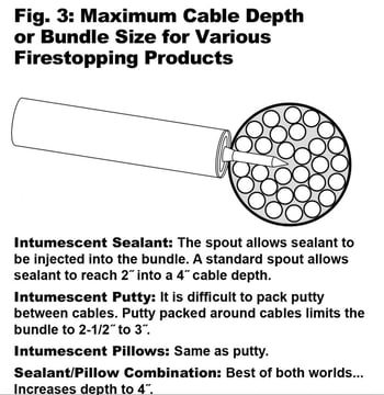
The choice of firestopping product form and materials technology also influences potential cable loadings: Product Forms influence cable loadings by virtue of their methods of installation (See Fig 3 & 4). Sealants can be caulked into and around cable bundles. Putties are installed by hand packing around the cable bundle. Pillows are also installed by inserting into the opening around the cable bundle. Products that install around the bundle naturally limit the percentage of cable fill.
Materials Technology: In broad terms, there are two types of materials used for firestopping based upon their reaction to the application of heat or flames:
Intumescent Materials: During a fire cable jackets burn away. The conductors collapse together and the overall size of the cable bundle shrinks. Intumescent materials (materials that expand when exposed to fire or heat) properly used, can compensate for this loss of mass. Thus they tend to be the product of choice for sealing cable penetrations. These products are amazing but they can’t be expected to work miracles. You still need to get some of it in the hole. Each cable added to a penetration displaces some of the firestop system. There is a point of no return for every type of product.
The intumescent material must be installed in a way that permits it to push in and compress the cable bundle. Looking at the cable trays in Figure 5, while the loading percentages are identical, the cable tray on the top will require less compression than the cable tray on the bottom. Thus it will be easier and safer to firestop. When it comes to firestopping,
maximum cable depth or cable bundle diameter is a better and safer method of measurement than percentages of cross sectional area.
Passive Firestopping Materials: Intumescent products can put the squeeze on cables. Non-intumescent materials also referred to as passive materials, depend upon either heat sinking (drawing heat away) or insulating to afford fire protection to combustible penetrants. Designs utilizing passive materials must generally be thicker and will have a far more limited range in terms of the types and amounts of cables that they can protect. Mortars, silicone sealants and foam, and some grout products fall into this category. Because of the limitations of these products and our focus on retrofittable systems, we will not spend any more time discussing these types of products in this presentation.
 Sleeves or No Sleeves: No, this isn’t a fashion statement! People often ask us about whether sleeves are required or not. For low voltage data and telecom applications, sleeves are optional and not mandatory. Sleeves serve two functions. From an aesthetics standpoint, sleeves give the penetration a more finished look. From a mechanical standpoint, sleeves provide a soft spot in a wall or floor intended to be an easy portal for cables to penetrate. Sleeves are often used as forms in concrete floors to conveniently create the openings for cables as the concrete is poured. Sleeves may extend above the level of the floor to prevent water from potentially entering a penetration or they may be raised to provide a mechanical bumper to protect the penetrants and the penetration.
In wall penetrations, we suggest sleeves for hollow wall construction. The sleeve provides a container for the firestop system. When packing materials are required, the sleeve
prevents them from simply falling into the wall cavity. When pillows are used, the smooth surface of the sleeve makes pillow installation easier and helps contain and focus the pillows expansion energy. Sleeves provide little or no advantage in solid wall applications.
Over-Sized Sleeves Vs. Spare Sleeves:
When it comes to sleeved cable penetrations planning works better than magic. In these applications, having too much up your sleeve will eventually cause major headaches. Proper planning gives you a number of choices in terms of preparing for future expansion of a facility’s cabling. If you are using sleeves, you can oversize them as we have already discussed or you can install empty spares. Since even your present estimate for cable growth will prove to be a conservative figure (It always does! ) a combination of oversizing and spares would probably be prudent.
Types of Sleeves:
I suppose we could categorize sleeves any number of ways. Right now, I’ll stick to two general types that refer mostly to cable installation. If the sleeve is to be installed prior to installation of the cables, a solid sleeve may be used. If the cables have been installed first, a split sleeve or two-piece sleeve is required to allow the sleeve to be installed around the cable bundle.
Cable Trays Carry The Load!
More and more, we are seeing cable trays used to carry the load when it comes to the huge amounts of data and telecom wiring used in a modern building. Trays can carry more cable than conduit. Trays also make cable changes easier. A number of new tray types have been introduced in recent years that are aimed at this market. Center hung tray and wire basket types are just two tray types that have become widely used for data and telecom cable distribution. When it comes to cable trays, we suggest the use of trays that allow the firestop materials to come into contact with the cables both top and bottom. We do not recommend solid bottom cable trays for use in a retrofittable environment.![]()
Cable Distribution in Trays:
Cables should be distributed evenly in trays. Don’t pile the cables up on one side. Cable depth in a tray is similar to cable bundle size. Follow the guidelines shown in Fig. 5. When firestopping with pillows, try to avoid cable gaps that would create openings in the installation. Where such gaps are unavoidable, use putty to fill them in.
Cable Tray Depth:
As you’ve already seen, firestopping imposes certain loading limits on cable trays. Since the limitation is depth of the cables, consider this fact carefully when purchasing or specifying cable trays. Don’t buy 6” tray when the firestop system is only effective with a 2-1/2” or 3” cable depth. Not only will the space be wasted, but additional
cables almost certainly will be installed at a later date which could neutralize the effectiveness of the firestop system. Save the money and buy cable trays that are more appropriate in terms of loading depth. Save additional money on the firestops by making the required openings smaller to boot!
Product Combinations
Reduce Firestopping Costs:
Tray openings (especially multiple tray openings) are usually a great deal larger than required to run the tray itself. The area within the tray is designed to carry the cables. The area around the trays can usually be sealed using a less expensive, more permanent method. Firestop mortar around the tray and pillows within the tray area provide an economical solution for these firestop applications while maintaining ease of retrofit.
Cable Support:
You can’t expect any cable to be self-supporting and you shouldn’t expect the firestop to do the job either! Proper cable support is a must in a firestop system. Don’t allow slack cable in the vicinity of a penetration. This is particularly critical in floor installations. If the firestop has been installed tightly to the cables, sagging cables can pull the firestop out of the floor. Make sure the cables are supported above the firestop system in floor applications and on both sides of wall penetrations.
Cable Penetration Expert:
Congratulations! You’ve made it. You now know just about everything there is to know about cable penetration firestop design. Using the guidelines provided above, you will be a hero to everyone in the future who has to modify the cables in the installations that you have designed. You’ve not only handled the facility’s present firestopping problems… You’ve provided for its needs for many years to come.